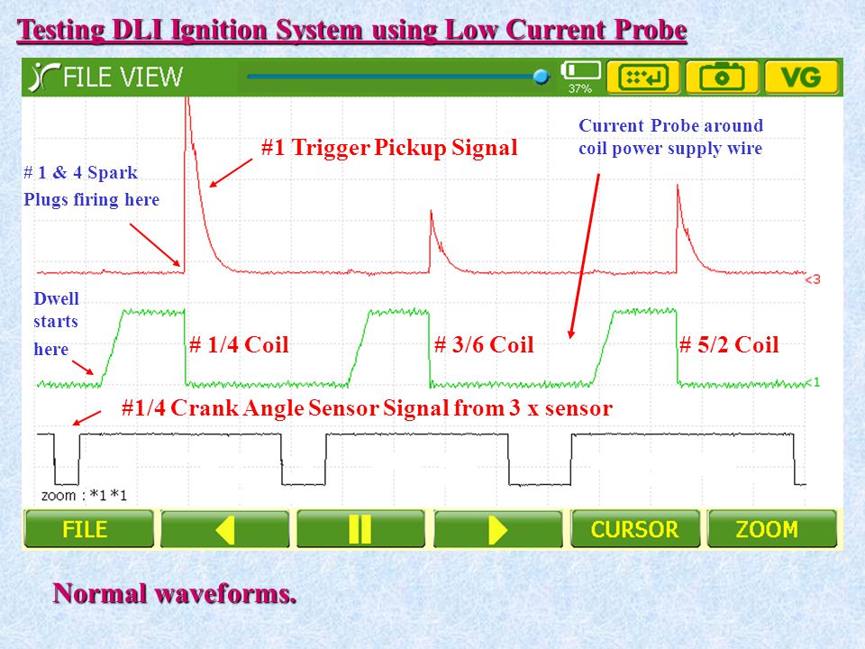
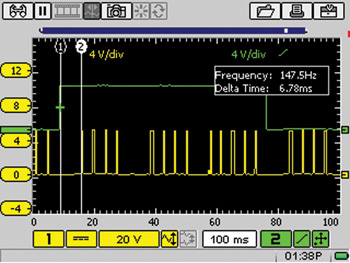
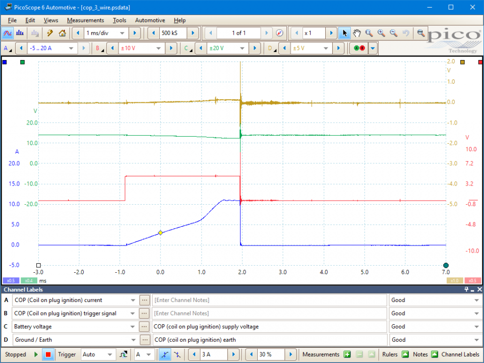
Currently Backordered! Use the AES Primary Ignition Lead with the Vantage PRO, MODIS, and VERUS to see the primary ignition spikes that rise higher than 200 volts while maintaining the option to zoom in on essential details such as the dwell, burn time and coil oscillations. As the engine speed increases, the dwell angle expands to maintain a constant coil saturation time and therefore constant energy. The coil sat u ration time can be measured by placing one time ruler at the beginning of the dwell period and the other at the end of the current ramp.
Actuator information

| Type: | Coil on plug |
|---|---|
| Power supply: | 12 V, from system relay |
| Signal type: | Frequency varying |
| Signal level: | - |
Workings of a coil on plug ignition

With Coil On Plug (COP) ignition, each spark plug has its own ignition coil, directly mounted on the spark plug, without spark plug cables. Like in all ignitions systems, the coils transform a low voltage on the primary side to a high voltage on the secondary side to produce a spark across the contacts of the spark plug.
Three different COP ignition systems are available:
Dwell Lab Scope Coil Kit
- 2 wire COP ignition
An ignition coil which is entirely controlled by ECU - 3 wire COP ignition
An ignition coil with a controller module on it which is triggered by the ECU via the third wire - 4 wire COP ignition
Same as the 3 wire COP but with extra control wire to ECU for feedback/diagnostic purposes
Each system requires a different measuring technique, but using the Coil-on-Plug probe TP-COP750, all systems can be measured with a single measurement setup.
Connecting the lab scope

Dwell Lab Scope Coil Tester
With COP, no spark plug cables are present to clamp an ignition pickup on. To measure these signals, the Coil-on-Plug probe TP-COP750 can be used. The Coil-on-Plug probe TP-COP750 is connected to the lab scope using a Measure lead TP-C1812B and the lab scope is set to normal scope mode with the following input setting:
| Channel | Probe | Voltage | Range |
|---|---|---|---|
| 1 | COP probe | 2 V | |
| Leave unconnected |

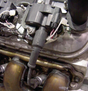
Simply place the probe on the coil, as can be seen in Figure 1 and the secondary ignition patterns become visible on your oscilloscope and can be analyzed.
Measuring
Figure 2 shows a waveform of a COP ignition of a car with idling engine. This signal can be downloaded and used to correctly set up the lab scope or as reference signal.
Channel 1 (red) in figure 2 shows the signal from a 4 wire COP ignition measured with the Coil-on-Plug probe TP-COP750. The signal shows the typical waveform of an ignition system. On the left side it starts with the module switching on the coil to build up a magnetic field. When ignition has to take place, the module switches off the coil and the magnetic field that is built up collapses and creates a high voltage in the secondary winding of the coil, this is the high spike in the signal. The high voltage creates a spark that sustains until the energy in the coil has become too low, which can be seen in the signal dropping.
Diagnosis
Dwell Lab Scope Coil Placement
Signal values may differ on different types of engine control units and COP ignition. Consult ATIS for information on specific engine control units and COP ignitions.

The following signal deviations can indicate a problem:
- No signal:
Cause: position of the Coil-on-Plug probe TP-COP750 is not correct, no power supply to COP ignition, no trigger signal from ECU - Signal voltage too low:
Cause: position of the Coil-on-Plug probe TP-COP750 is not correct, poor power supply to COP ignition - Noisy signal:
Cause: GND wire of the measure lead is connected, leave this unconnected
- Honda Jazz holds back and stalls
- A 2006 Honda Jazz with L13A i-DSI engine occasionally holds back and sometimes even stops.No error codes were stored in the car.Several components have been replaced or swapped with an other car.A lot was driven in the car with a scanner hooked up to monitor the 'live data' to find ananomaly in sensor or actuator data.Nothing showed up.Only after diagnosing with a good automotive diagnostic oscilloscope, the cause of the problemswas revealed.
- Ford F150 with defective ignition coil
- A Ford F150 has an ignition coil for each cylinder and one of them is defective. It is replaced by a new one, but that one breaks down within half an hour. It is replaced again, with the same result. Measuring with an automotive oscilloscope and a current clamp reveal that the ignition control module is defective.
This document is subject to changes without notification. All rights reserved.
The information in this application note is carefully checked and is considered to be reliable, however TiePie engineering assumes no responsibility for any inaccuracies.
Safety warning:
- Before measuring, check that sources of dangerously high voltages are switched off or shielded from contact. Voltages considered to be dangerous are voltages over 30 V AC RMS, 42 V AC peak or 60 V DC.
- Keep a clean working environment when doing measurements.
- This measurement and procedures are a examples / measuring suggestions and are no prescribed protocols.
- TiePie engineering can not anticipate the safety actions that need to be taken to protect persons and appliances. Before starting a measurement, check which safety measures need to be applied.